
Sequence Diagram
The sequence diagram is used primarily to show the interactions between objects in the sequential order that those interactions occur. Much like the class diagram, developers typically think sequence diagrams were meant exclusively for them.
The diagram purpose
The sequence diagram is used primarily to show the interactions between objects in the sequential order that those interactions occur. Much like the class diagram, developers typically think sequence diagrams were meant exclusively for them. However, an organization's business staff can find sequence diagrams useful to communicate how the business currently works by showing how various business objects interact. Besides documenting an organization's current affairs, a business-level sequence diagram can be used as a requirements document to communicate requirements for a future system implementation. During the requirements phase of a project, analysts can take use cases to the next level by providing a more formal level of refinement. When that occurs, use cases are often refined into one or more sequence diagrams.
An organization's technical staff can find sequence diagrams useful in documenting how a future system should behave. During the design phase, architects and developers can use the diagram to force out the system's object interactions, thus fleshing out overall system design.
One of the primary uses of sequence diagrams is in the transition from requirements expressed as use cases to the next and more formal level of refinement. Use cases are often refined into one or more sequence diagrams. In addition to their use in designing new systems, sequence diagrams can be used to document how objects in an existing (call it "legacy") system currently interact. This documentation is very useful when transitioning a system to another person or organization.
The notation
Since this is the first article in my UML diagram series that is based on UML 2, we need to first discuss an addition to the notation in UML 2 diagrams, namely a notation element called a frame. The frame element is used as a basis for many other diagram elements in UML 2, but the first place most people will encounter a frame element is as the graphical boundary of a diagram. A frame element provides a consistent place for a diagram's label, while providing a graphical boundary for the diagram. The frame element is optional in UML diagrams; as you can see in Figures 1 and 2, the diagram's label is placed in the top left corner in what I'll call the frame's "namebox," a sort of dog-eared rectangle, and the actual UML diagram is defined within the body of the larger enclosing rectangle.
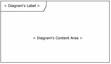
In addition to providing a visual border, the frame element also has an important functional use in diagrams depicting interactions, such as the sequence diagram. On sequence diagrams incoming and outgoing messages (interactions) for a sequence can be modeled by connecting the messages to the border of the frame element (as seen in Figure 2). This will be covered in more detail in the "Beyond the basics" section below.
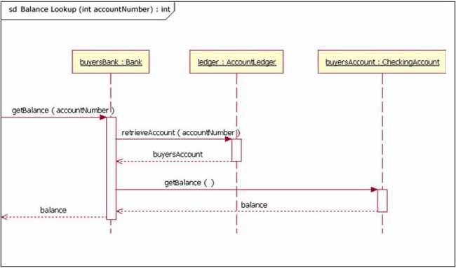
Notice that in Figure 2 the diagram's label begins with the letters "sd," for Sequence Diagram. When using a frame element to enclose a diagram, the diagram's label needs to follow the format of:
The UML specification provides specific text values for diagram types (e.g., sd = Sequence Diagram, activity = Activity Diagram, and use case = Use Case Diagram).
The basics
The main purpose of a sequence diagram is to define event sequences that result in some desired outcome. The focus is less on messages themselves and more on the order in which messages occur; nevertheless, most sequence diagrams will communicate what messages are sent between a system's objects as well as the order in which they occur. The diagram conveys this information along the horizontal and vertical dimensions: the vertical dimension shows, top down, the time sequence of messages/calls as they occur, and the horizontal dimension shows, left to right, the object instances that the messages are sent to.
Lifelines
When drawing a sequence diagram, lifeline notation elements are placed across the top of the diagram. Lifelines represent either roles or object instances that participate in the sequence being modeled. (Note: In fully modeled systems the objects (instances of classes) will also be modeled on a system's class diagram.) Lifelines are drawn as a box with a dashed line descending from the center of the bottom edge (Figure 3). The lifeline's name is placed inside the box.
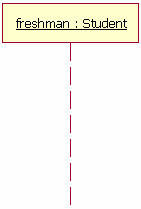
The UML standard for naming a lifeline follows the format of:
In the example shown in Figure 3, the lifeline represents an instance of the class Student, whose instance name is freshman. Note that, here, the lifeline name is underlined. When an underline is used, it means that the lifeline represents a specific instance of a class in a sequence diagram, and not a particular kind of instance (i.e., a role). In a future article we'll look at structure modeling. For now, just observe that sequence diagrams may include roles (such as buyer and seller) without specifying who plays those roles (such as Bill and Fred). This allows diagram reuse in different contexts. Simply put, instance names in sequence diagrams are underlined; roles names are not.
Our example lifeline in Figure 3 is a named object, but not all lifelines represent named objects. Instead a lifeline can be used to represent an anonymous or unnamed instance. When modeling an unnamed instance on a sequence diagram, the lifeline's name follows the same pattern as a named instance; but instead of providing an instance name, that portion of the lifeline's name is left blank. Again referring to Figure 3, if the lifeline is representing an anonymous instance of the Student class, the lifeline would be: "Student." Also, because sequence diagrams are used during the design phase of projects, it is completely legitimate to have an object whose type is unspecified: for example, "freshman."
Messages
The first message of a sequence diagram always starts at the top and is typically located on the left side of the diagram for readability. Subsequent messages are then added to the diagram slightly lower then the previous message.
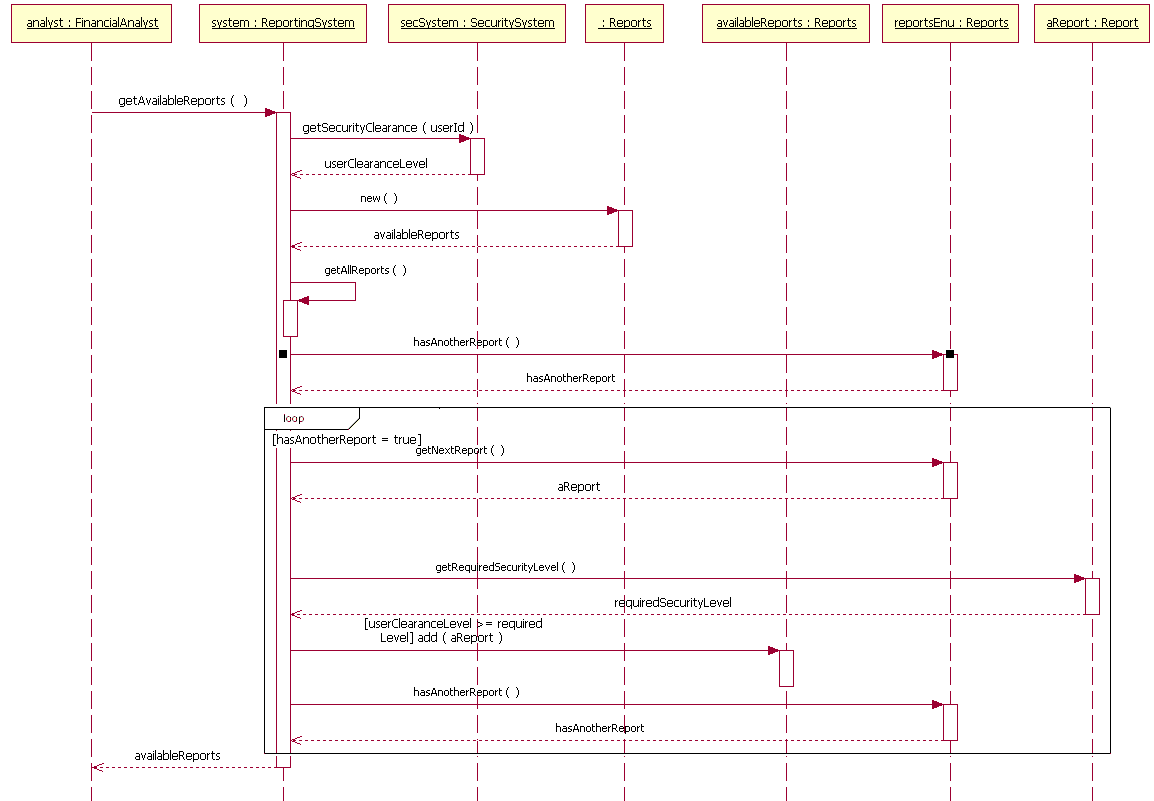
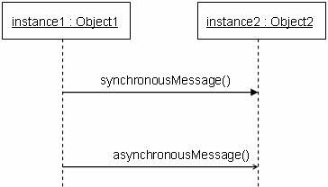
To show an object (i.e., lifeline) sending a message to another object, you draw a line to the receiving object with a solid arrowhead (if a synchronous call operation) or with a stick arrowhead (if an asynchronous signal). The message/method name is placed above the arrowed line. The message that is being sent to the receiving object represents an operation/method that the receiving object's class implements. In the example in Figure 4, the analyst object makes a call to the system object which is an instance of the ReportingSystem class. The analyst object is calling the system object's getAvailableReports method. The system object then calls the getSecurityClearance method with the argument of userId on the secSystem object, which is of the class type SecuritySystem. (Note: When reading this sequence diagram, assume that the analyst has already logged into the system.)
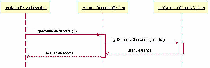
Besides just showing message calls on the sequence diagram, the Figure 4 diagram includes return messages. These return messages are optional; a return message is drawn as a dotted line with an open arrowhead back to the originating lifeline, and above this dotted line you place the return value from the operation. In Figure 4 the secSystem object returns userClearance to the system object when the getSecurityClearance method is called. The system object returns availableReports when the getAvailableReports method is called.
Again, the return messages are an optional part of a sequence diagram. The use of return messages depends on the level of detail/abstraction that is being modeled. Return messages are useful if finer detail is required; otherwise, the invocation message is sufficient. I personally like to include return messages whenever a value will be returned, because I find the extra details make a sequence diagram easier to read.
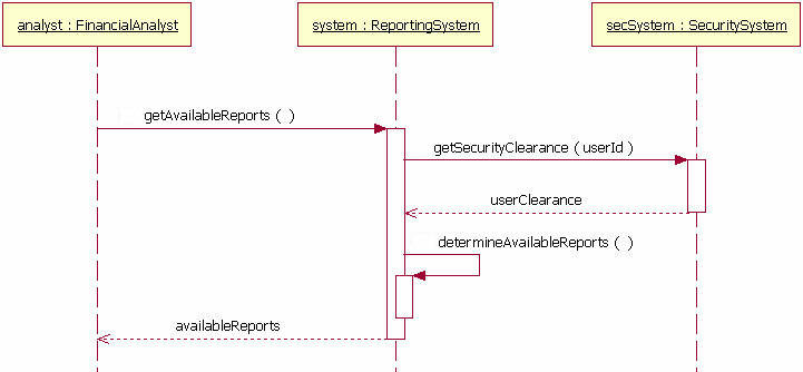
When modeling a sequence diagram, there will be times that an object will need to send a message to itself. When does an object call itself? A purist would argue that an object should never send a message to itself. However, modeling an object sending a message to itself can be useful in some cases. For example, Figure 5 is an improved version of Figure 4. The Figure 5 version shows the system object calling its determineAvailableReports method. By showing the system sending itself the message "determineAvailableReports," the model draws attention to the fact that this processing takes place in the system object.
To draw an object calling itself, you draw a message as you would normally, but instead of connecting it to another object, you connect the message back to the object itself.
The example messages in Figure 5 show synchronous messages; however, in sequence diagrams you can model asynchronous messages, too. An asynchronous message is drawn similar to a synchronous one, but the message's line is drawn with a stick arrowhead, as shown in Figure 6.
Guards
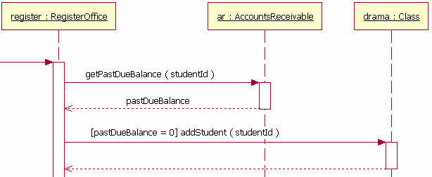
When modeling object interactions, there will be times when a condition must be met for a message to be sent to the object. Guards are used throughout UML diagrams to control flow. Figure 7 shows a fragment of a sequence diagram with a guard on the message addStudent method.
Summary and next steps
The sequence diagram is a good diagram to use to document a system's requirements and to flush out a system's design. The reason the sequence diagram is so useful is because it shows the interaction logic between the objects in the system in the time order that the interactions take place.
Comments (0)
No comments yet.